U1713 - convert ARINC 429, ASCB, analogs and more

U1713

Digital Interface Module


The U1713 is a Line Replaceable Module with a fast processor which is programmed at a very low-level. Core Drivers provide basic IO interfaces through the ports, enabling speedy development of the Hosted Application.

There are endless use cases:

  • convert ARINC 429 to ASCB to install an AHRS
  • use the U1713 as an Engine Data Concentrator, receive tachs and temperatures and output the data on ARINC 429
  • record flight data for Flight Operations Quality Assurance (FOQA)
  • adapt new avionics to resolve obsolesce of existing equipment
  • custom CDU controls & interfaces

Canaan Avionics offers loaner equipment and blue/red label configurations to get your STC started easy and fast. We help you reverse engineer, develop the requirements, and cross the finish line –

Specs

Dimensions — 5.7 × 4.0 × 1.1" (see the model in downloads)

Weight — 0.85 lbs

Power Input — 28 VDC nominal (15 VDC min to 32 VDC max). 110 mA nominal (*more current if directly running currents from Discrete IO). Circuit Breaker: 1 Amp.

TSO — C113B [pending]

Software DAL — DO-178C Level B/A (depending on the Hosted Application requirements)

Environmental Qualification — DO-160G, categories suitable for pressurized and non-pressurized environments in Part 25 aircraft (see full table below).

Connectors — 104-pin Mil-Spec D-Sub (J1), with optional additional 44-pin connector (J2) when a daughter card is installed.

Processor — 200 MHz ARM CPU — no complex devices, no operating system, no ASICs or FPGA, single core/thread. Simple processor/interface class module per AC 20-152.

Hosted Application

The U1713 module is configured through a Hosted Application that both provides port configuration and functionality. Canaan Avionics developed a custom previously-approved kernel to control the hardware, making the Hosted Application development lightweight and efficient.

The unit has a single loadable software part that executes on a 200 MHz ARM CPU. The U1713 contains no complex hardware as defined by AC 20-152, meaning that it is a simple processor/interface class module. Software on the device configures and has access to all of the ports available and drives all of the Signal Types.

Developing the Hosted Application typically starts with an STC project. Canaan Avionics can either receive requirements from the end-user (such as the STC owner) or Canaan Avionics can generate requirements for the end user and provide them to be part of the STC project.

U1713 Hosted Application architecture

Application Notes

The Application Notes provide a system-level configuration of the U1713 and how it interfaces with other systems in the architecture. Each U1713 configuration has an Application Note which serves to specifically identify the interfaces, provide a block diagram, pin-outs, and notes for the functional aspects of the software. This is how the highest-level functionality is communicated, and how this installation information is supplemented.

Example U1713 Application Note

The Application Note identifies the ports used and how they are wired to other systems. The STC developer uses the Application Note (and this installation information) to develop detailed Installation Drawings and to help develop Ground Test Plans and Flight Test Plans. Canaan Avionics uses the Application Note to communicate and validate the software functionality.


Certification Objectives

The U1713 is a previously certified platform with the hardware qualified to DO-160G, software processes approved under TSO/PMA according to DO-178C. The Hosted Application provides functionality that is certified at the aircraft level, under the TC/STC.

ARP-4754, Guidelines for Development of Civil Aircraft and Systems is one of many acceptable means for stitching together aircraft-level functional requirements with sub-systems, such as the U1713. ARP-4754 compliance is not required for most projects, but it does establish a requirement traceability concept that both verifies and validates functionality of the whole aircraft as a system.

See Certification Process for more information regarding the typical U1713 data package, the cert objectives, and how these processes dovetail into the aircraft-level design approvals.


Dimensions

U1713 Dimensions

Ports

- The most ports in the smallest package -

- total of 104 Pins, plus a 44 Pin Daughter Card for additional ports. Each port is software controlled, and the configuration is defined in the Application Note for the completed module.


SIGNAL_IN
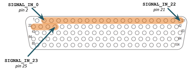
SIGNAL_IN_X Ports

SIGNAL_IN_X ports are multi-purpose inputs. Each can be configured as one of the following types:

Ground/Open Input: A ground [or voltage below 1.8 volts] is a logical TRUE.

28V/Open Input: A voltage greater than 2.8 volts is a logical TRUE.

DC Analog Input: A 12-bit DC analog signal can be measured at 20Hz. The voltage range must be positive in relation to the signal ground, ranging from 0-6VDC.

Note: All Signal inputs have the configurable DC Analog Input range as described, except inputs 20-thru-23 which are only discretes.

Frequency Counting: Given any voltage threshold desired, as defined by the DC Analog Input configuration, inputs can be configured as frequency counting for any frequency ranging from 0-100KHz. This type of configuration can be used for signals such as Engine Tach or Fuel Flow.


GND_DISC_OUT
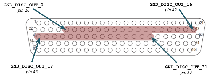
GND_DISC_OUT_X Ports

These are discrete outputs that are capable of providing Ground/Open signals with one of the following configurations:

Ground/Open Output: A ground signal capable of providing a constant 200mA output for running relays or annunciators.

Note: The total for all outputs across all GND/Open Discrete Outputs should be less than 3.0 amps nominally for reasons of heat generation.

Ground/Open SENSE: Some of the GND_DISC_OUT also have a piggybacked ground/open input, which can be used as either an input (like a SIGNAL_IN) or for safety critical aspects where the GND_DISC_OUT needs to be monitored from function and/or reported for a Continuous Built-In Test (CBIT).


SENSE_IN
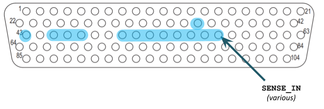
SENSE_IN Ports

SENSE_IN are piggybacked on ports that have a “+”, such as the GND_DISC_OUT_[X] + and PASS_THRU_[X] + ports. SENSE_IN ports can be used as a discrete input or a frequency counter. A common use for the SENSE_IN_[X] ports is for position strapping of the unit or for wrap-around verification that GND_DISC_OUT_[X] outputs are operating reliably for safety-critical applications.


V_DISC_OUT
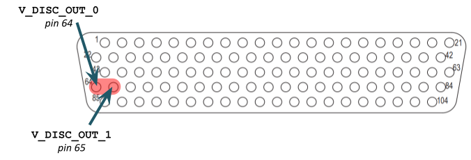
V_DISC_OUT_X Ports

These ports are capable of providing 25V/Open signals with a constant 300mA output for running relays, valid flags, or annunciators. They are high-side-fet driven, providing a source for clicking relays, or for providing NAV Superflags.

Note: If there are V_DISC_IN pins, then the V_DISC_OUT draws current from power input to those pins. Apply power to the V_DISC_IN port by either splicing into the main box power or by powering through a separate 1 amp circuit breaker.


ANALOG_IN
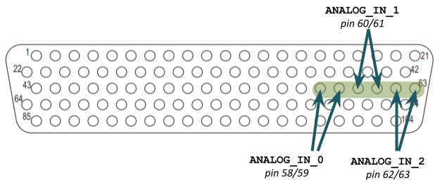
ANALOG_IN_X Ports

Precision Analog inputs are capable of receiving a 24 bit voltage from -3 to 48VDC. The precision of these is fine enough to be used for temperature thermocouples, flight control position sensors, current sensors/shunts, 150mA Deviations. These are differential amplified and isolated from ground. Maximum read frequency is 100Hz depending on the application.


A429_RX(TX)

Note: There are more ARINC 429 ports on daughter cards, but just showing J1 ports in this diagram.
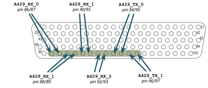
A429_RX(TX)

The U1713 framework implements a full software controlled A429 “stack”. The software drivers offer full control to mix and match any label, SDI, and parity on the same bus. Each port is capable of independently transmitting and receiving a maximum of 2,777 words per second. Words can be scheduled to be transmitted in a particular order, or queued when the software is ready to transmit them. Layered protocols are supported such as ARINC 615 or ARINC 708. Ports can be configured as either High Speed (100 kBits/sec) or Low Speed (12.5 kBits/sec).


RS422_RX(TX)
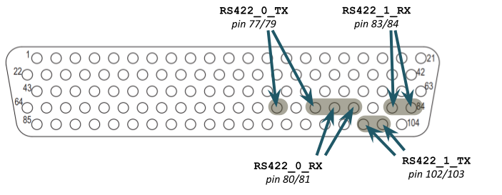
RS422_RX(TX)

RS-422 ports can be configured to support a number of commercial/industrial signal types such as RS-422/485. Collins Serial Data Bus (CSDB) is also supported. Signals can be software controlled through standard UART exchanges or “bit-banged” for unique protocols, such as control panel signals or even Honeywell data buses.

Note: ModBus, CAN Bus and other protocols are supported through these ports and other dedicated means through daughter cards.


RS232_RX(TX)
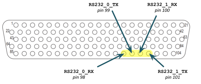
RS232_RX(TX)

RS-232 signals can be software controlled through standard UART exchanges or can support non-synchronous communication.


- other Supported Types through various daughter cards include...

ASCB Honeywell Avionics Standard Communications Bus
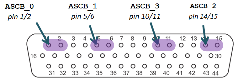
ASCB

ASCB ports support end systems on an ASCB network. The ASCB may be one or more end systems on the network (such as an AHRS), or may be the bus controller (such as the autopilot or symbol generator). The ASCB ports support versions A/B/C and the ASCB clock in the case of ASCB version A. The ASCB ports can be configured for other Honeywell protocols, such as Radio Select Bus (RSB).


AC_SIGNAL_OUT

This is a software-controlled AC output capable of transmitting AC signals such as [not limited to]:

  • ARINC-407
  • Synchro-servo
  • 393mV/degree pitch and roll commands

Note: Most AC_SIGNAL_OUT applications require that the AC_REFERENCE_IN be wired to 26VAC reference.


DC_SIGNAL_OUT

This is a software-controlled 16-bit DC output capable of transmitting DC signals such as [not limited to]:

  • 150mA Navigation Deviations
  • Radio Altitude Analogs
  • AHRS Accelerometer Outputs
  • Control Surface Positions for Flight Data Recorder Interfaces

CAN_BUS

This is a software-controlled dual-channel CAN interface capable of transmitting and receiving CAN messages such as [not limited to]:

  • Standard and extended identifier frames
  • Data rates up to 1 Mbps
  • ARINC 825-compatible traffic

Note: The CAN ports support both classic CAN 2.0A/B and can be configured for ARINC 825 operation.


Provisionally the U1713 intends to implement other protocols such as Ethernet, ARINC 664/AFDX, and MIL-STD-1553. If you don’t see the protocol you need, just let us know.

Main Board (J1 Connector)

The J1 connector is the main connector and is always used for a U1713 integration. J1 contains the power inputs and most of the basic Port Types. The U1713 may also be configured with daughter cards to add more ports, and often there is a J2 connector associated with each daughter configuration.

Connector Kit: K210724-1 (Canaan Avionics)

J1 Pin-out

PinDescription PinDescription PinDescription PinDescription
1PWR_28VDC27GND_DISC_OUT_153GND_DISC_OUT_27 +79RS422_TX_0_L
2SIGNAL_IN_028GND_DISC_OUT_254GND_DISC_OUT_28 +80RS422_RX_0_H
3SIGNAL_IN_129GND_DISC_OUT_355GND_DISC_OUT_29 +81RS422_RX_0_L
4SIGNAL_IN_230GND_DISC_OUT_456GND_DISC_OUT_30 +82CHASSIS_GND
5SIGNAL_IN_331GND_DISC_OUT_557GND_DISC_OUT_31 +83RS422_RX_1_H
6SIGNAL_IN_432GND_DISC_OUT_658ANALOG_IN_0_H84RS422_RX_1_L
7SIGNAL_IN_533GND_DISC_OUT_759ANALOG_IN_0_L85RTN_28VDC
8SIGNAL_IN_634GND_DISC_OUT_860ANALOG_IN_1_H86A429_RX_0_A
9SIGNAL_IN_735GND_DISC_OUT_9 +61ANALOG_IN_1_L87A429_RX_0_B
10SIGNAL_IN_836GND_DISC_OUT_1062ANALOG_IN_2_H88A429_RX_1_A
11SIGNAL_IN_937GND_DISC_OUT_1163ANALOG_IN_2_L89A429_RX_1_B
12SIGNAL_IN_1038GND_DISC_OUT_1264V_DISC_OUT_090A429_RX_2_A
13SIGNAL_IN_1139GND_DISC_OUT_1365V_DISC_OUT_191A429_RX_2_B
14SIGNAL_IN_1240GND_DISC_OUT_1466CHASSIS_GND92A429_RX_3_A
15SIGNAL_IN_1341GND_DISC_OUT_1567PASS_THRU_0 +93A429_RX_3_B
16SIGNAL_IN_1442GND_DISC_OUT_1668PASS_THRU_1 +94A429_TX_0_A
17SIGNAL_IN_1543GND_DISC_OUT_17 +69PASS_THRU_2 +95A429_TX_0_B
18SIGNAL_IN_1644GND_DISC_OUT_1870PASS_THRU_3 +96A429_TX_1_A
19SIGNAL_IN_1745GND_DISC_OUT_19 +71PASS_THRU_4 +97A429_TX_1_B
20SIGNAL_IN_1846GND_DISC_OUT_20 +72CHASSIS_GND98RS232_0_RX
21SIGNAL_IN_1947GND_DISC_OUT_21 +73PASS_THRU_5 +99RS232_0_TX
22SIGNAL_IN_2048GND_DISC_OUT_2274PASS_THRU_6 +100RS232_1_RX
23SIGNAL_IN_2149GND_DISC_OUT_23753.3V_OUT101RS232_1_TX
24SIGNAL_IN_2250GND_DISC_OUT_24 +765V_OUT102RS422_TX_1_H
25SIGNAL_IN_2351GND_DISC_OUT_25 +77RS422_TX_0_H103RS422_TX_1_L
26GND_DISC_OUT_052GND_DISC_OUT_26 +78CHASSIS_GND104PASS_THRU_7 +

Note: Ports with a + sign are also SENSE_IN ports.


Environmental Qualification (DO-160G)

Condition DO-160G Section Equipment Qualifications & Categories
Temperature and Altitude4.0(A2)(F2)
Low Operating Temperature4.5.1−55 °C
High Operating Temperature4.5.3+70 °C
Low Storage Temperature4.5.1−55 °C
High Storage Temperature4.5.2+85 °C
In-Flight Loss of Cooling4.5.4X
Altitude4.6.155,000 feet
Temperature Variation5.0B
Humidity6.0B
Shock7.0B
Operational Shock7.26 g peak
Crash Safety Impulse7.3.120 g peak
Crash Safety Sustained7.3.218 g min
Vibration8.0S(C)(L)(M)
Explosion Proofness9.0E
Waterproofness10.0Y
Fluids Susceptibility11.0X
Sand and Dust12.0X
Fungus Resistance13.0F (Modified)
Salt Spray14.0X
Magnetic Effect15.0Z
Power Input16.0Z
Voltage Spike17.0A
Audio Frequency Conducted Susceptibility18.0Z
Induced Signal Susceptibility19.0ZC
RF Susceptibility20.0W
Emissions of RF Energy21.0M
Lightning Induced Transient Susceptibility22.0B3G3L3
Lightning Direct Effects23.0X
Icing24.0X
Electrostatic Discharge25.0A (Modified)
Fire Flammability Test26.0C (Modified)

Aircraft Wiring

Various wiring types may be permitted with the U1713, determined by the installer and the design/installation approvals at the STC level. However, the U1713 often performs safety-critical applications in environments that may have significant Electromagnetic Interference (EMI). For this reason, Canaan Avionics recommends using wire types that meet or exceed the wire with which the U1713 was qualified.

Gauge Single Single-Shielded Twisted-Shielded ASCB / RSB
22 M22759/16-22-9 M27500-22TG1T14 M27500-22TG2T14 X
24 M22759/16-24-9 M27500-24TG1T14 M27500-24TG2T14 ECS PN: 322402

Notes:

  • All wiring except for the power and grounding should be shielded if the U1713 performs safety-related functions.
  • All wiring except for the power and grounding should be 24 Gauge.
  • Ground shields using ring terminals into the backshell. Keep shield terminations shorter than 3”.

Pro Tip: If there are a lot of signals used with your U1713 configuration (such as analog inputs), consider using 24 ga shielded wiring. The U1713 has 104 pins, and the inputs are low-current, meaning that a large wire size is often overkill and can lead to a large wire harness as the number of I/O increases. A 22 ga wire can carry current protected by a 5amp circuit breaker (see AC 43.13-1B ). A signal input to the U1713 will never draw more than a few milliamps (outputs might draw more current). If the wiring needs to be shielded, then 24 ga should be considered a balance between mechanical strength, crimp-ability, and wire harness size constraints. Most 20 ga contacts can be crimped onto a 24 ga wire per specification.


Mechanical — Mounting, Orientation & Bonding

The U1713 can be mounted using #6 screws through the top or using #10 screws through the bottom side. The metal surface under the U1713 should be bare metal for bonding reasons (not painted/non-conductive). Bonding should be verified by measuring impedance between the J1 connector jackscrew and the aircraft metal surface.

U1713 Mounting Screws

There are weep holes in the enclosure sides, meaning that the U1713 should be mounted in a vertical orientation where possible so that condensation can migrate to the side and egress the enclosure.

Note: Mounting in all orientations is possible, but depends on the environment. Contact Canaan Avionics for orientations that were tested and qualified for certain environments if not in the shown orientation.

The P1 (and P2 if present) connectors shall be supported with a saddle clamp or other wire harness support directly to the airframe. This is because vibrations induced into the wire harnesses can stress the U1713 connector which can translate to stress on the internal components. The wire harnesses must be supported to structure immediately outside of the enclosure to prevent this prolonged damage.

Chassis Grounds should be bonded to the aircraft structure as close as possible to the connector, preferably not to a mounting screw.

U1713 Orientation